Description
After many failed attempts to follow Lesson #12 in the Sunfounder Super Kit and even more frustrated with the Sunfounder website, I decided to publish my findings for the dot-matrix experiment because a) I forget and b) maybe someone else will find this useful. The correct tutorial can ultimately found on youtube. The whole playlist seems to be more useful than the booklet, the PDF in the super kit download and the Sunfounder forum or website. But that’s all part of the fUn!
Like my previous experiment, this experiment uses the shiftOut function to write to 2 74HC595 chips. One chip controls the dot-matrix columns while the other controls the rows.
The dot-matrix display that comes with the super kit is an 8 x 8 monochrome (red) LED matrix, model number 1588bs. I couldn’t find a data-sheet for this model and it was unclear which side was top or bottom and therefore which pins were the column pins and which were the row pins. What I found is that the side which I ultimately deemed the bottom row had the model number stamped on it along with a rounded-tab like protrusion in the middle.

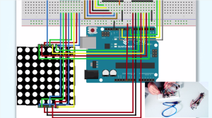
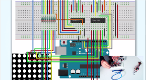
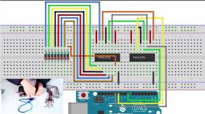
Breadboard View
Code
The code in the download seemed to be slightly different and didn’t work with the breadboard connections I ultimately used. The download had some extra junk code and was missing the logical negation values passed as the last argument to the shiftOut function. The calls to delay for even one millisecond seemed to slow down the display to a painful crawl, so I removed them.
const int latchPin = 8;//Pin connected to ST_CP of 74HC595
const int clockPin = 12;//Pin connected to SH_CP of 74HC595
const int dataPin = 11; //Pin connected to DS of 74HC595

int data[] = {0xFF,0xFF,0xFF,0xFF,0xFF,0xFF,0xFF,0xFF,/*" ",0*/
              0xFF,0xC1,0xBE,0xBE,0xBE,0xC1,0xFF,0xFF,/*"0",1*/
              0xFF,0xDF,0xDF,0x80,0xFF,0xFF,0xFF,0xFF,/*"1",2*/
              0xFF,0xDC,0xBC,0xBA,0xB6,0xCE,0xFF,0xFF,/*"2",3*/
              0xFF,0xDD,0xBE,0xB6,0xB6,0xC9,0xFF,0xFF,/*"3",4*/
              0xFB,0xF3,0xEB,0xDB,0x80,0xFB,0xFF,0xFF,/*"4",5*/
              0xFF,0x8D,0xAE,0xAE,0xAE,0xB1,0xFF,0xFF,/*"5",6*/
              0xFF,0xC1,0x96,0xB6,0xB6,0xD9,0xFF,0xFF,/*"6",7*/
              0xFF,0xBF,0xBC,0xB3,0xAF,0x9F,0xFF,0xFF,/*"7",8*/
              0xFF,0xC9,0xB6,0xB6,0xB6,0xC9,0xFF,0xFF,/*"8",9*/
              0xFF,0xCD,0xB6,0xB6,0xB4,0xC1,0xFF,0xFF,/*"9",10*/
              0xFC,0xF3,0xCB,0x9B,0xEB,0xF3,0xFC,0xFF,/*"A",11*/
              0xFF,0x80,0xB6,0xB6,0xB6,0xB6,0xC9,0xFF,/*"B",12*/
              0xFF,0xE3,0xDD,0xBE,0xBE,0xBE,0xBE,0xDD,/*"C",13*/
              0xFF,0x80,0xBE,0xBE,0xBE,0xBE,0xDD,0xE3,/*"D",14*/
              0xFF,0x80,0xB6,0xB6,0xB6,0xB6,0xBE,0xFF,/*"E",15*/
              0xFF,0x80,0xB7,0xB7,0xB7,0xB7,0xBF,0xFF,/*"F",16*/
              0xFF,0xFF,0xFF,0xFF,0xFF,0xFF,0xFF,0xFF,/*" ",0*/};
void setup ()
{
  //set pins to output
  pinMode(latchPin,OUTPUT);
  pinMode(clockPin,OUTPUT);
  pinMode(dataPin,OUTPUT);
}
void loop()
{

  for(int n = 0; n < 136; n++)
  {
    for(int t = 0;t < 100;t ++)
    {
      int dat = 0x01;
      for(int num = n; num < 8+ n; num++)
      {
          //shift to simulate right to left scrolling
          dat = dat<<1;

          shiftOut(dataPin,clockPin,MSBFIRST,~data[num]);
          shiftOut(dataPin,clockPin,MSBFIRST,~dat);

          //return the latch pin high to signal chip that it
          //no longer needs to listen for information
          //pull the latchPin to save the data
          digitalWrite(latchPin,HIGH);

          //ground latchPin and hold low
          //for as long as you are transmitting
          digitalWrite(latchPin,LOW);
      }
    }
  }
}